
- 4 mA is live zero: a broken wire reads 0 mA and is therefore detectable as a fault, not a valid reading.
- Check the whole loop — field device, wiring, barrier, input card, controller scaling and the operator display.
- Record five points up and down, note hysteresis, and keep calibrator traceability with the sheet.
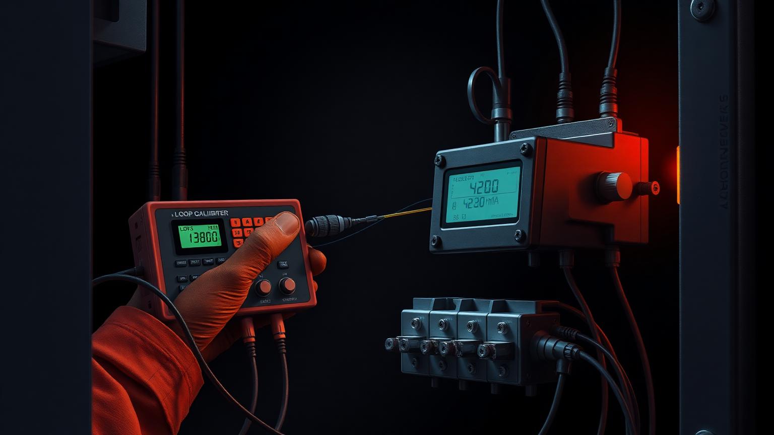
A loop check proves that a physical quantity in the field arrives correctly on an operator's screen. It is not a transmitter calibration, and it is not a wiring buzz-out. It is the end-to-end test that catches the reversed pair, the wrong range in the DCS and the display still set to the previous project's units.
Why 4–20 mA, and why live zero matters
The analogue current signal is standardised in IEC 60381-1, which defines 4–20 mA DC as the interface between transmitter and receiver.[1] Because the bottom of scale is 4 mA and not 0 mA, an open circuit is distinguishable from a valid minimum reading. NAMUR NE 43 builds on this by reserving ≤3.6 mA and ≥21 mA for diagnostic failure signalling, so an instrument can announce its own failure inside the same two wires.[2] Check what your input card does with those bands before you commission the loop.
If the loop forms part of a safety instrumented function, the check is also a proof test and its interval, coverage and results are governed by IEC 61511-1. Do not fold it into a routine commissioning sheet.[3]
The procedure
Loop check, field to screen
Confirm the work permit, isolation state and that the loop is out of service. Where the loop drives a final element, agree with the control room how the output is defeated and who restores it.
| % of span | Injected | Expected EU | Tolerance |
|---|---|---|---|
| 0% | 4.000 mA | Range minimum | ±0.1% of span |
| 25% | 8.000 mA | ¼ of span | ±0.1% of span |
| 50% | 12.000 mA | Mid-span | ±0.1% of span |
| 75% | 16.000 mA | ¾ of span | ±0.1% of span |
| 100% | 20.000 mA | Range maximum | ±0.1% of span |
Tolerance is a project decision, not a universal number: it is set from the accuracy class on the datasheet and the terminology and performance definitions in ANSI/ISA-51.1, which is where terms such as span, zero, hysteresis and repeatability are formally defined.[6] Descending readings expose hysteresis that an ascending-only test hides.
Sign-off pack
Common questions
Why is 4 mA used as live zero?
Because a broken wire reads 0 mA. With a live zero, the absence of signal is distinguishable from a genuine zero reading, so an open circuit is detectable as a fault rather than accepted as a valid measurement.
What does a full loop check cover?
Every hop: field device, wiring, barrier, input card, controller scaling, alarms and interlocks, and the operator display. A loop proved only at the input card has not been proved to the person who has to act on it.
How many points should be recorded?
Five points, up and down, with hysteresis noted, and the calibrator's traceability recorded on the same sheet. Traceability under ISO/IEC 17025 is what makes the reading evidence rather than an anecdote.
Are safety-instrumented loops checked differently?
Yes. Loops in a safety-instrumented function are governed by IEC 61511 and carry their own proof-test requirements, documented separately from a routine process loop check.
Sources for every claim above
Each footnote in the article links here. Standards are cited by designation so you can verify the current edition with the issuing body.
- [1]IEC 60381-1 — Analogue signals for process control systems: Direct current signalsIEC · International Electrotechnical Commission · 1982 (with amendments)View source
- [2]NE 43 — Standardisation of the signal level for the failure information of digital transmittersNAMUR · NAMUR (User Association of Automation Technology in Process Industries) · 2003 (rev.)View source
- [3]IEC 61511-1:2016+AMD1:2017 — Functional safety: Safety instrumented systems for the process industry sectorIEC · International Electrotechnical Commission · 2017View source
- [4]ISO/IEC 17025:2017 — General requirements for the competence of testing and calibration laboratoriesISO/IEC · International Organization for Standardization · 2017View source
- [5]IEC 62381:2012 — Automation systems in the process industry: Factory, site and integration acceptance tests (FAT, SAT, SIT)IEC · International Electrotechnical Commission · 2012View source
- [6]ANSI/ISA-51.1-1979 (R1993) — Process Instrumentation TerminologyISA · International Society of Automation · 1993View source